Since this chapter does not yet exist, this is less of a summary than a chance to convey some new stuff.
An amplifier is a circuit that increases the size of a signal.
Amplifiers come in three types depending on their output.
Voltage Amplifiers are by far the most common. The output and
input are both voltages. A good voltage amplifier draws little or no
current from its course and is not designed to deliver much current
to the load. The Gain of the amplifier is defined to be
Vout/Vin.
Current Amplifiers are somewhat less common than voltage
amplifiers and are usually found at the output of a system. A current
amplifier usually produces the same output voltage as its imput but
delivers a large current to the load while drawing little current
from its source. A current amplifier has a voltage gain of 1, Vout =
Vin, but delivers current gain Iout/Iin.
Power Amplifiers are not really a separate class since a power
amplifier is also a current and voltage amplifier. Its job is deliver
power to some load and its gain is defined as Pout/Pin. This is
really a term that describes the use of the amplifier rather than its
operation. Most power amplifiers are made up from a voltage amplifier
followed by a current amplifier. Note that, because P=I*V, every
voltage amplifier and every current amplifier is also a power
amplifier.
A good amplifier exhibits the property of linearity. A
linear amplifier increases the size of a signal without altering its
shape at all. Realistic amplfiers are never perfect and the output
differs from the input, usually in small ways. Most amplifiers
introduce two types of errors.
Noise is variation of the output signal that was not in the
input. This is usually a problem with small signals rather than large
signals. When the signal is a video signal the noise appears as snow
or banding on the screen. When the signal is an audio signal the
noise appears as hissing or rumbling sounds.
Distortion is an alteration of the shape of the signal. This
occurs when the simple linear relationship Vout = Const * Vin breaks
down. Some common kinds of distortion are clipping, when the extreme
values of the signal are cut off, and cross-over distortion, when the
output is incorrect when the input passed through zero. In an audio
signal distortion makes the sound harsh and, in extreme cases,
unrecognizable.
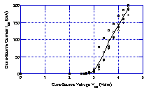
At the heart of every amplifier must be an active device, one that can use an external power source to increase the power in a signal. The active device that we have met is the FET. The basis of amplification is the transconductance curve of the FET. Here is the transconductance curve for our favourite 2N7000 n-channel MOSFET.

Above the threshold voltage, the curve is roughly a straight line with a slope that we call the transconductance, symbol gµ. In that region we can write IDS = gµ(VGS - VTh). This is a linear relationship, so long as gµ is constant, ie. to the extent that the line is really straight.
If we now pass the drain current through a resistor then we can convert the current into a voltage and we will have an amplifier. we get a circuit like this

Here a 1k drain resistor is shown. In general we will use a resistor of value R. In that case we can write an equation for Vout. The current in the resistor is given by IR = (15 - Vout)/R so that Vout = 15 - IDS * R. Thus if we substitute in the value of IDS from above we get Vout = 15 - gµ(VGS - VTh)*R. We can re-write this as
Vout = 15 + R*gµ*VTh - R*gµ*VGS so that Vout is linearly related to Vin and the system has a gain of R*gµ.
The problem with the system is that you need to add an offset to the input signal in order to get the amplifier above the threshold. You do this with a simple resistor circuit called a bias circuit.